Brake Disc Topology Optimization
Lightweight Formula Student rotor redesigned using topology + FEA validation.
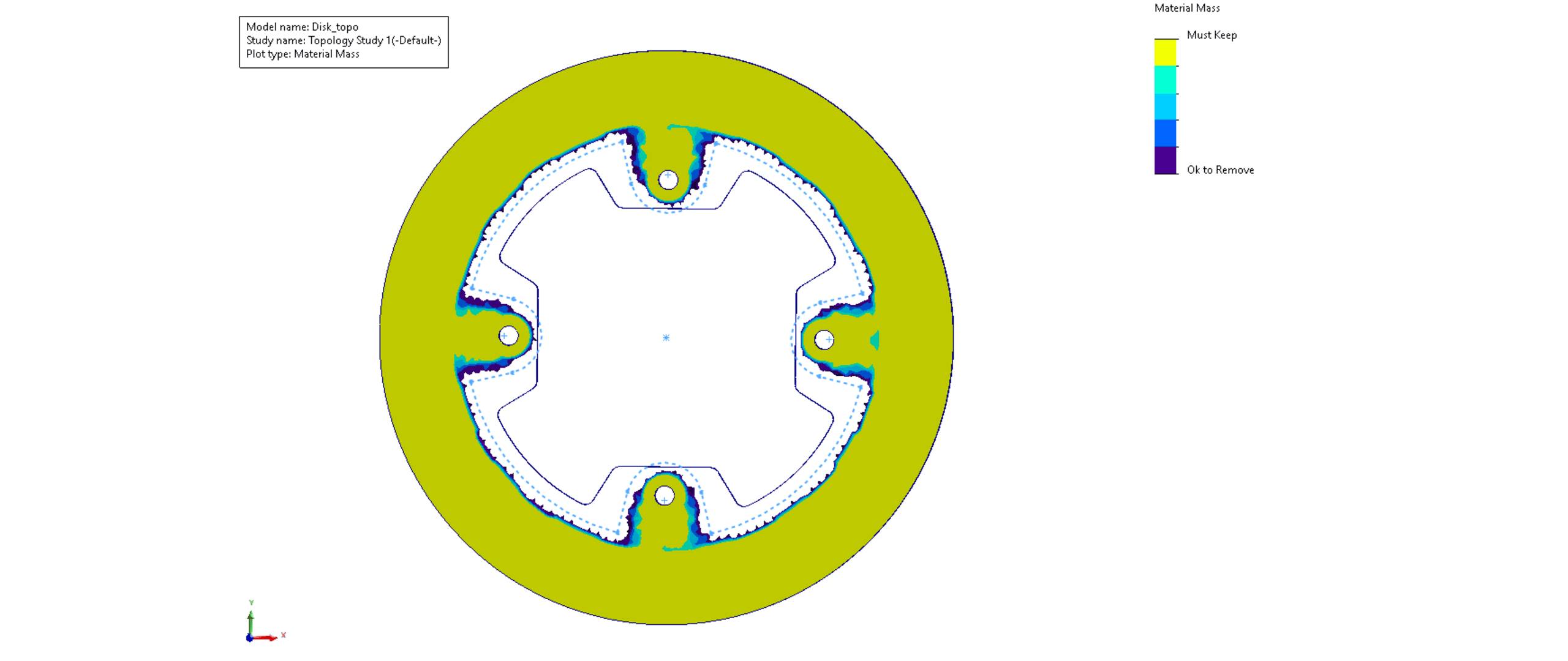
Built a baseline brake disc, ran topology optimization to remove non-critical material, redesigned a manufacturable geometry, then validated it in ANSYS using static structural (Von Mises / deformation) and transient thermal analysis to predict temperature rise during braking events.

1/7 — Geometry-driven design
/ Challenge
Reduce unsprung mass while ensuring stiffness and safe stresses under braking torque and heat.
/ Solution
Built a baseline rotor CAD, ran SolidWorks topology optimization to identify removable regions, then redesigned a manufacturable geometry and validated performance in ANSYS using static structural and transient thermal simulations.
/ Results
Delivered a lighter disc concept with controlled stress concentrations and limited deformation, plus quantified temperature rise & hotspots over time to support motorsport-oriented design decisions.
> Workflow guided by simulation-driven design
Topology optimization
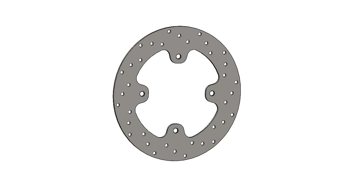
Manufacturable redesign
Static structural (ANSYS)
Transient thermal (ANSYS)
- MASS REDUCTION
- ≈ 15 %
- ROTOR GEOMETRY
- OD 200 mm · ID 140 mm · thickness 3 mm
- STRUCTURAL CASE
- Hub constraints · Tangential braking load · Total Hydraulic Pressure
- PEAK VON MISES
- 79.9 MPa (localized)
- THERMAL CASE
- Transient heat flux at pad interface · Convection on exposed surfaces
- PEAK TEMPERATURE
- 468°C during braking event